Production hall
Description of the hall and technological line
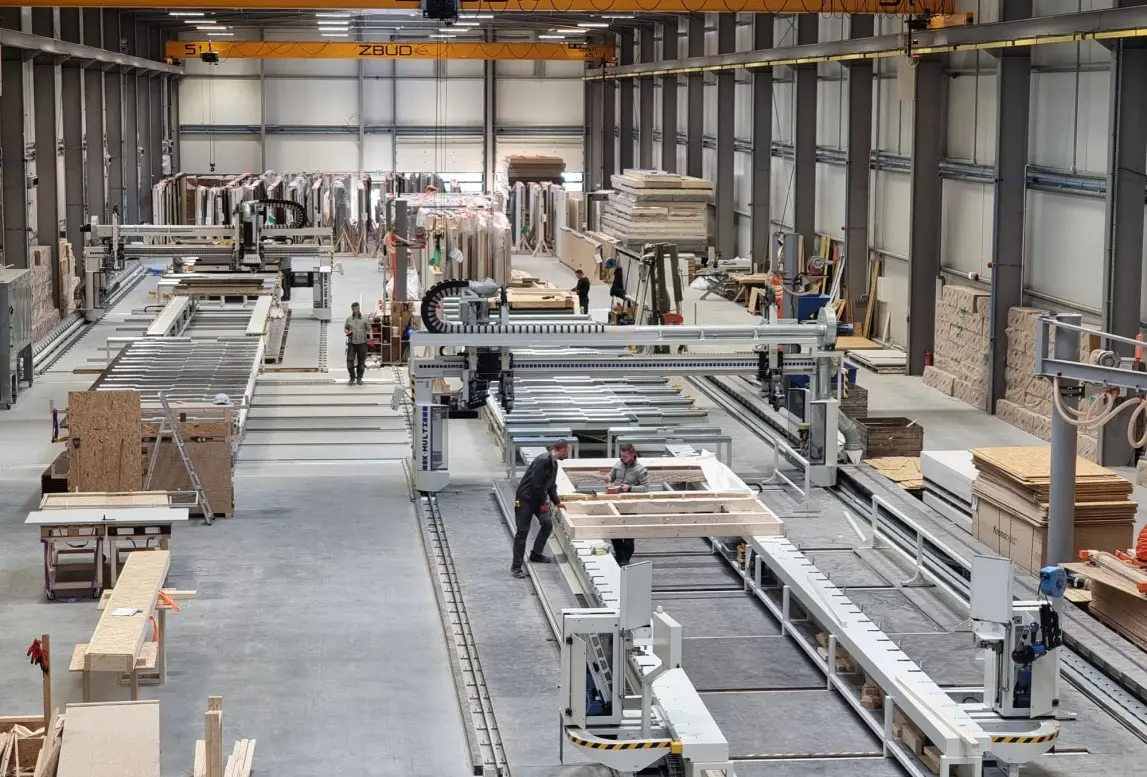
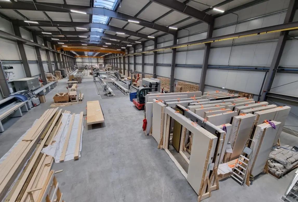
The Aristo Eco Home production hall with an area of 3,000 m 2 was built in 2021. The location of the hall is not accidental. The hall was built in the Łódź Special Economic Zone in the industrial district of Skierniewice, in the central part of Poland, from where there are very good transport connections. The close proximity of highways favors good logistic organization in cooperation with contractors.
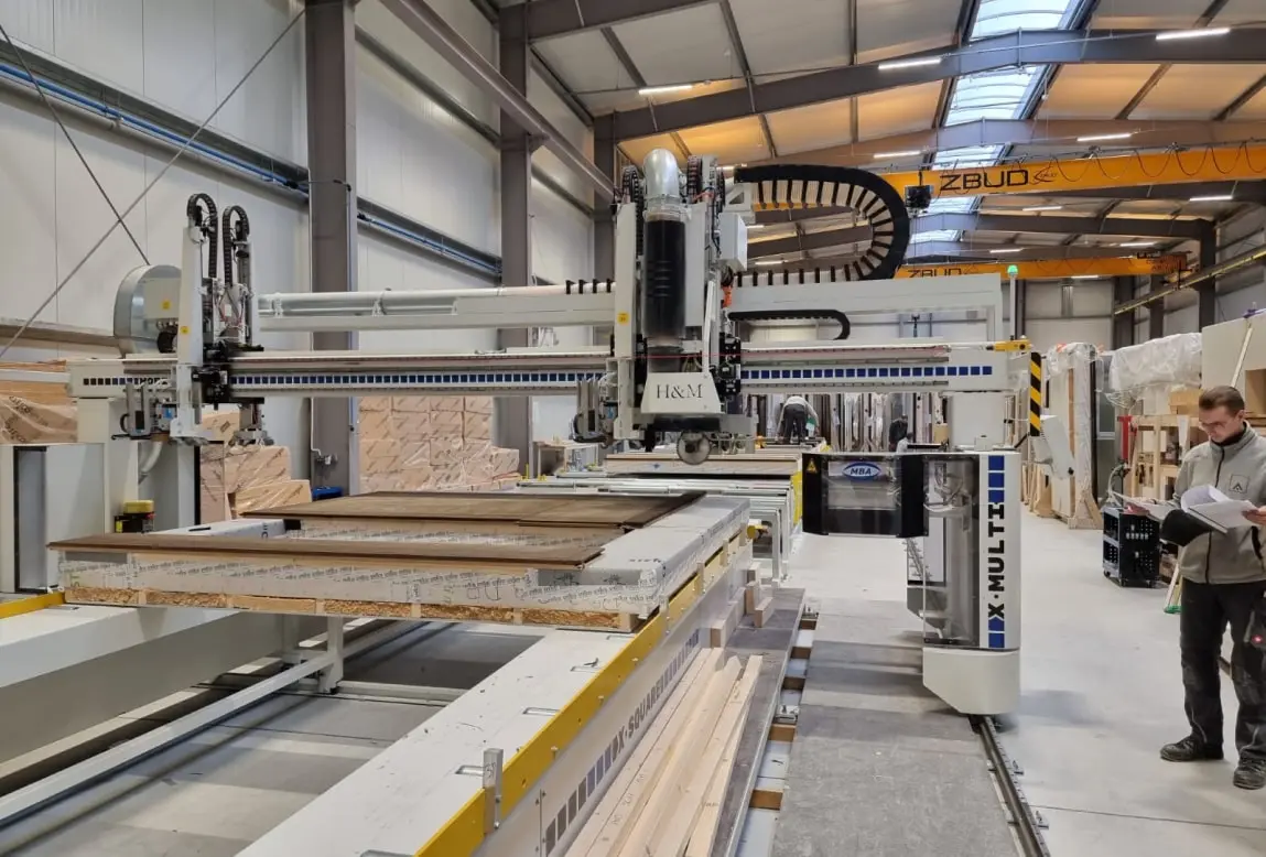
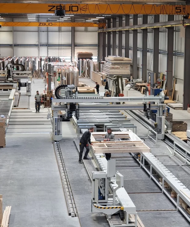
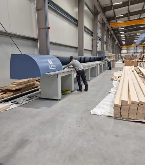
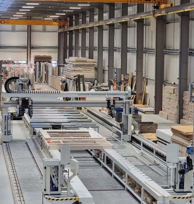
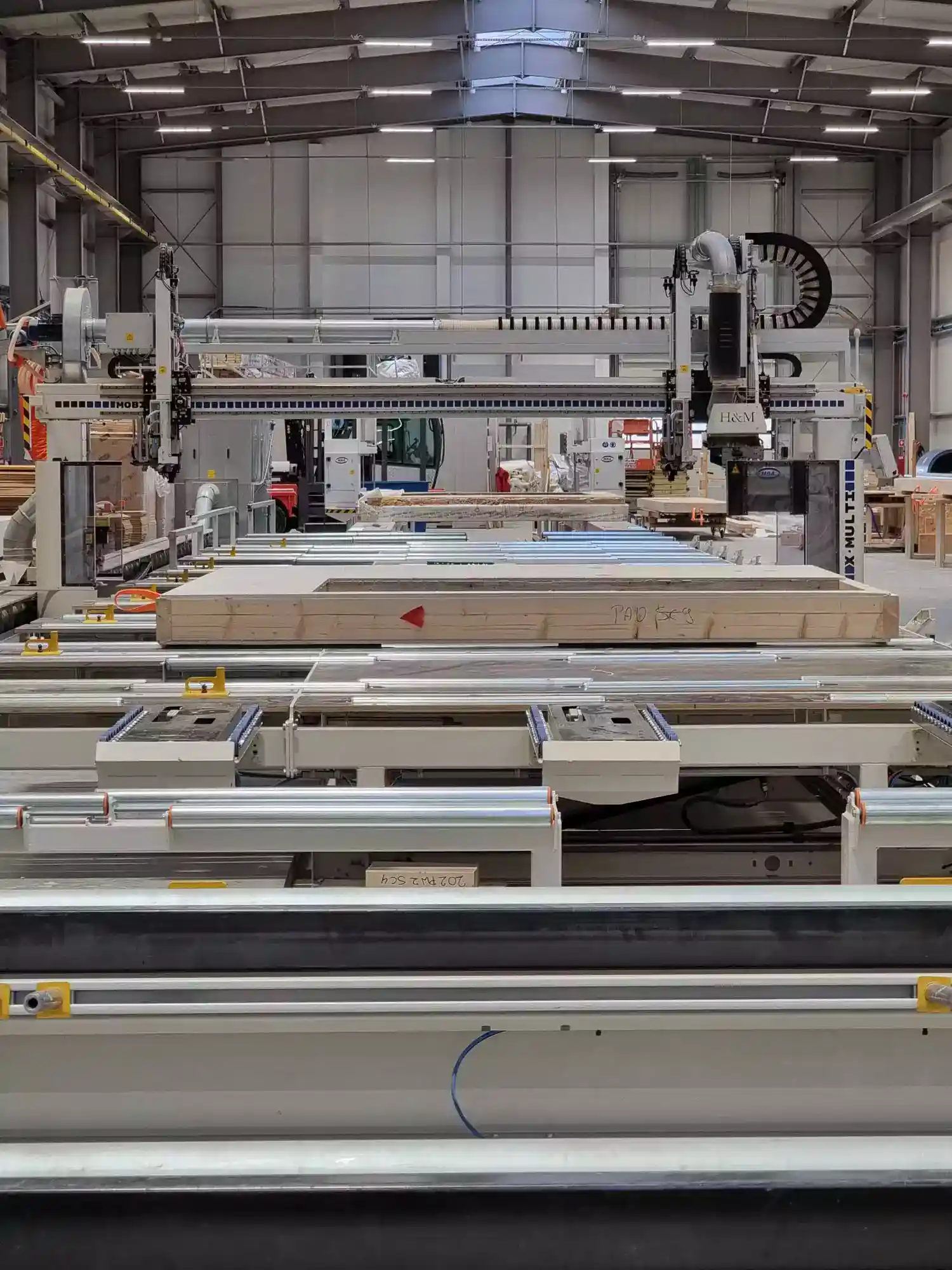
There is a numerically controlled line set up in the hall, starting from cutting wood for prefabrication, assembling the structure, covering the structure with boards, then cutting holes and cutting off the board protruding beyond the outline of the structure.
Dietrich's design program is used to design and later translate the completed project into the language of numerically controlled machining centers.
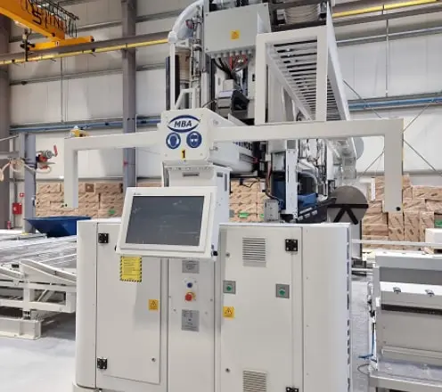
A. Cutting and milling center
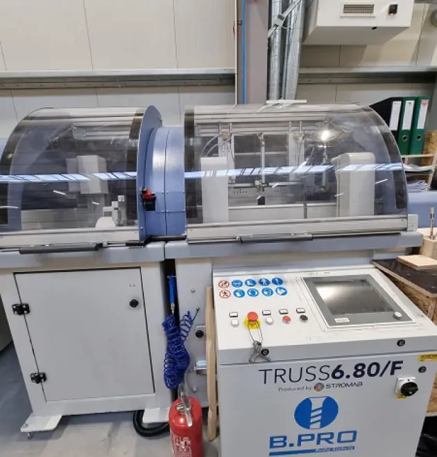
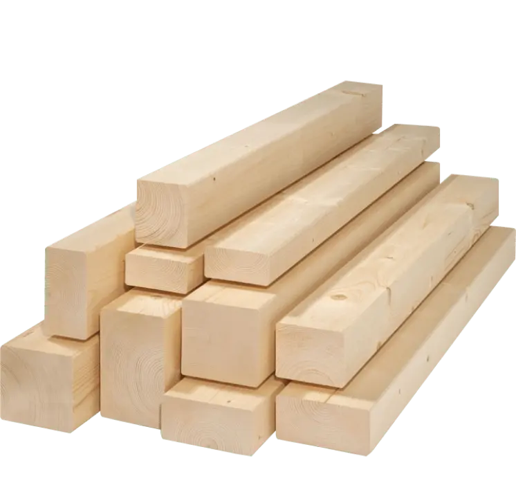
Raw material processed in the cutting line area:
B. Line for prefabrication of partitions
Station No. 1 for formatting the partition
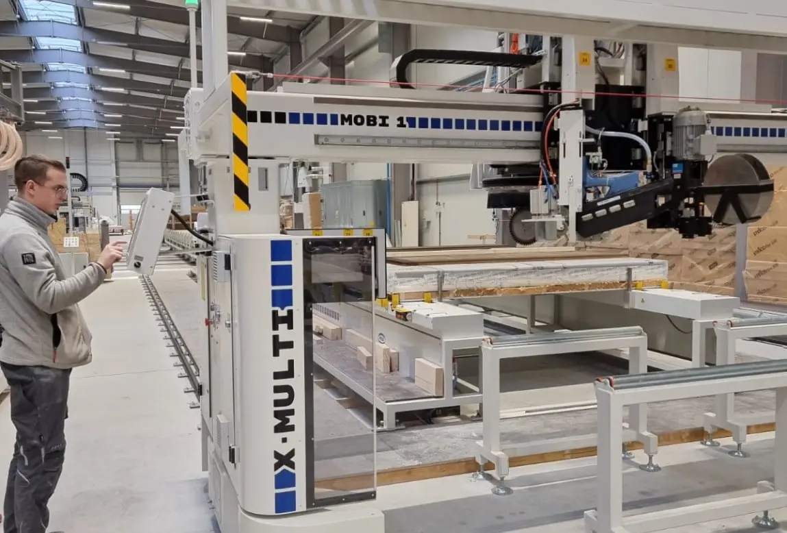
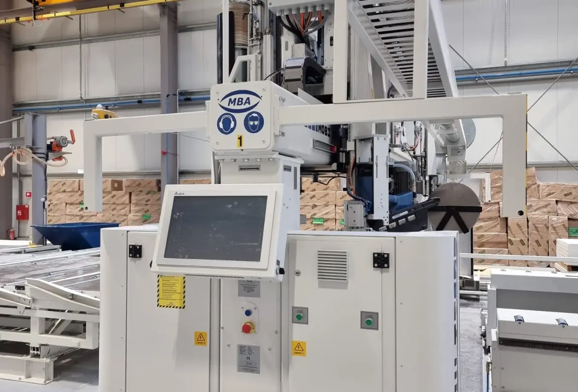
A numerically controlled sewing and milling bridge can move freely above the wall formatting table.
Work table No. 2 - internal partition covering
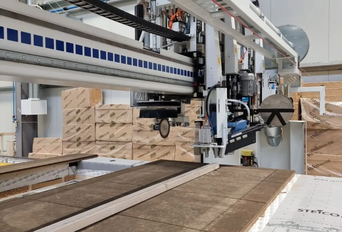
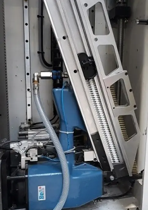
Sewing and milling bridge - Bridge "M1":
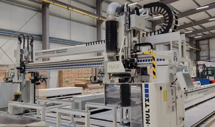
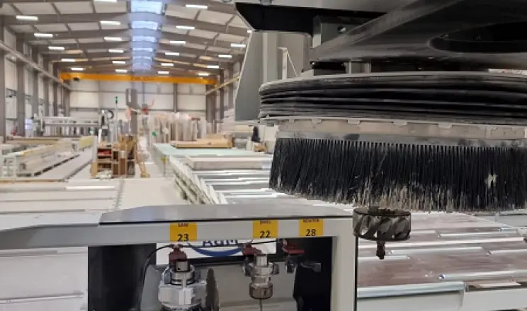
The following tools are located on the bridge beam:
Receiving table - table no. 3.
Work table no. 4
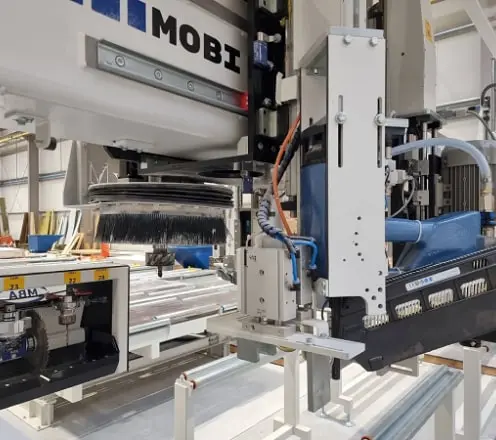
Sewing and milling bridge - "M2" bridge:
Work table no. 5
Work table no. 6
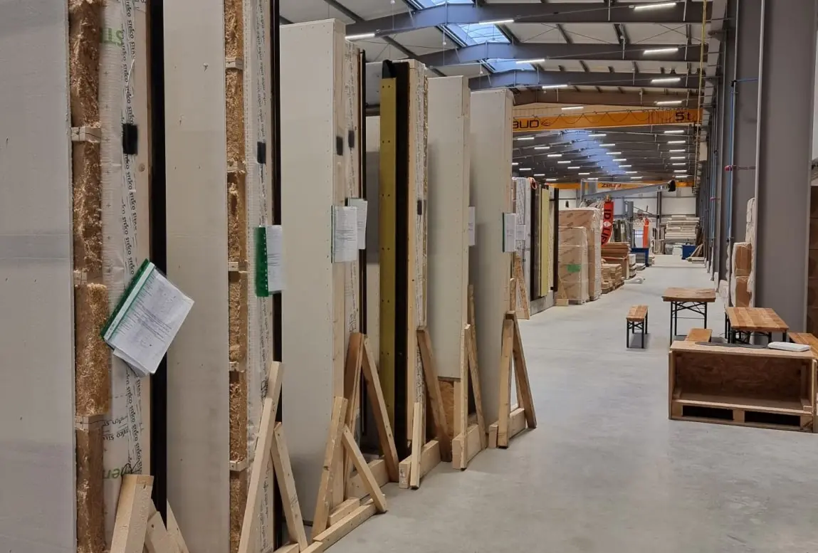
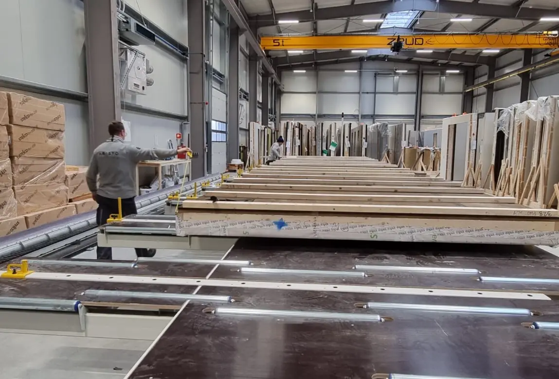
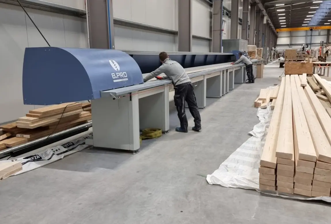
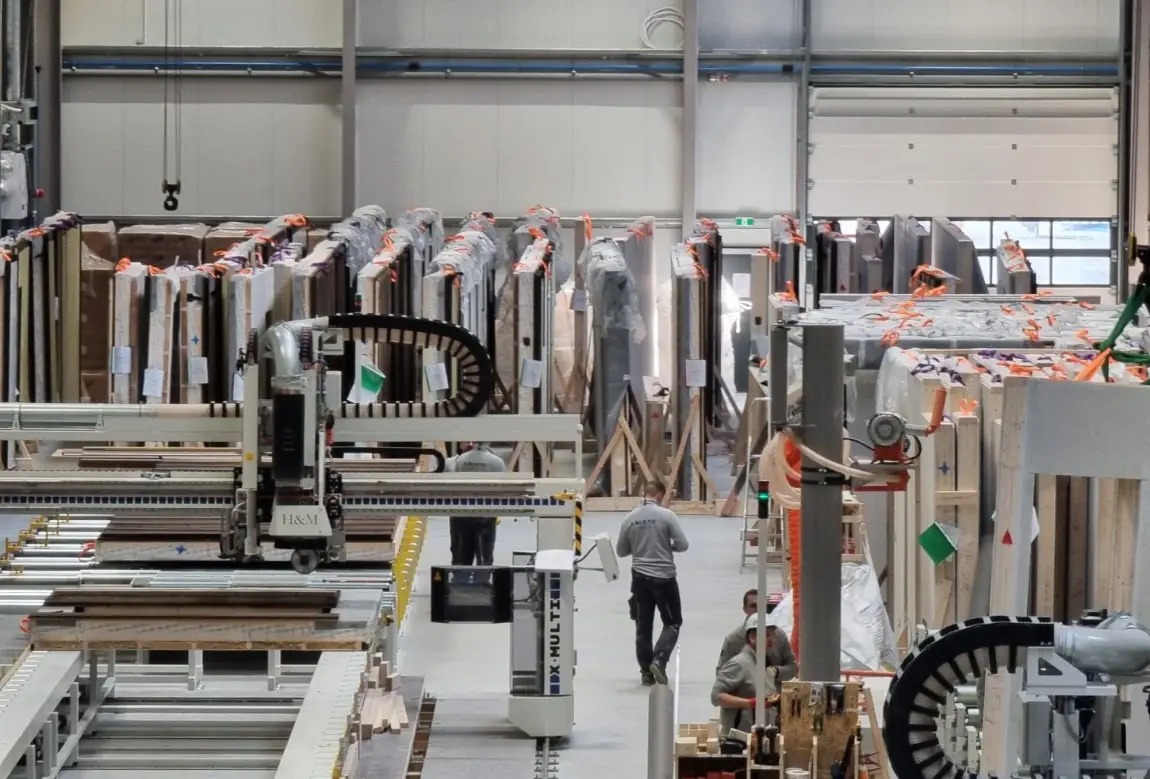
Gallery of the Production Hall and Technology Line